
Author:

Jirapongse Phuriphanvichai
Developer Advocate
Developer Advocate
Request Routing is a feature in EMA consumer applications that enables the establishment of multiple connections to upstream servers and directs market data item requests to the appropriate connection based on the service availability and operational status of each server. This feature also allows users to define service lists—named groupings of specific servers—which can be referenced in market data item requests. This feature also allows users to define service lists which are named groupings of particular server and users can use service lists with market data item requests. The SDKs then route the item request to a designated service within the service list, based on the ordered sequence of concrete service names and the connection list.
This feature is available in RTSDK C++ 2.3.0.L1 (EMA C++ 3.9.0.L1), RTSDK Java 2.2.3.L1 (EMA Java 3.8.3.L1) and RTSDK C# 2.3.0.L2 (EMA C# 3.4.0.L2). The request routing feature is only available in EMA.
This article explores four practical scenarios where this feature enhances real-time application capabilities.
Usage Scenarios
1. Consume Services from Multiple Servers
In some scenarios, a consumer application needs to retrieve data from multiple services hosted on different servers. For example, the application may need to subscribe to items from the ELEKTRON_DD service on Server A and from the DIRECT_FEED service on Server B.
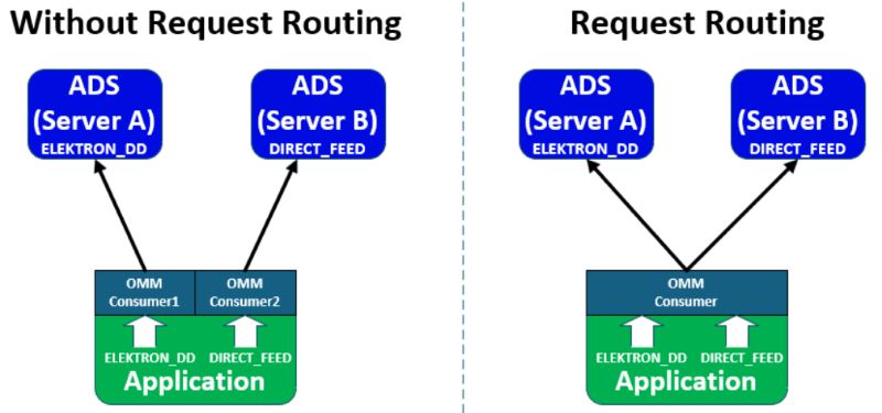
Figure 1: Connect to two ADS servers with and without the request routing feature
Without the request routing feature, the application must create two separate OMMConsumer instances—one to connect to Server A and another to Server B. The application is responsible for managing subscriptions to its respective service. For instance, the OMMConsumer connected to Server A would handle subscriptions to ELEKTRON_DD, while the one connected to Server B would manage subscriptions to DIRECT_FEED. This approach increases the complexity of the application, as it requires managing multiple consumer instances and their associated connections and subscriptions.
With the request routing feature, the application can use a single OMMConsumer instance to connect to both servers and consume data from both ELEKTRON_DD and DIRECT_FEED services. This significantly simplifies the architecture by reducing the need to manage multiple consumer instances.
2. Service Resilience
Users can leverage the request routing feature to improve service resilience. For example, EMA can be configured to connect to two servers that provide the same service (ELEKTRON_DD) using request routing. To ensure compatibility, the service attributes across both servers must match—specifically the supported Quality of Service (QoS) list, item list name, and QoS range support. If these attributes differ, the subsequent connection will be closed or removed based on the order of the session channel list.

Figure 2: Request Routing for Service Resilience
In the example above, the API establishes simultaneous connections to both Server A and Server B. Initially, it retrieves data from the ELEKTRON_DD service on Server A. If the connection to Server A fails, or if the ELEKTRON_DD service on Server A becomes unavailable, the API will automatically switch to retrieving data from the ELEKTRON_DD service on Server B.
3. Service Resilience with Service List
In some cases, services for the same data feed may have different names. For example, the LSEG real-time data feed on Server A may use the service name ELEKTRON_DD, while on Server B it may be named IDN_RDF. Although the names differ, both services deliver the same data.
To enable service resilience between these services, users can define a service list that includes the concrete service names used to request market data items. Requests made using the service list name are routed by the ordered list of concrete service names in the service list and the ordered list of connections in the configurations. All concrete services within a service list must support the same Quality of Service (QoS) to ensure compatibility.
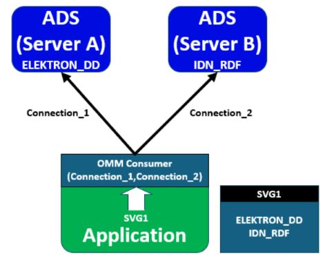
Figure 3: Service List
In the example shown above, an application defines a service list named SVG1, which includes the concrete services ELEKTRON_DD and IDN_RDF. The ELEKTRON_DD service is available on Server A, while IDN_RDF is available on Server B.
When subscribing to the SVG1 service, EMA attempts to match the specified service within a session channel by evaluating both the ordered list of concrete service names in the service list and the ordered list of connections. EMA will first try to use the ELEKTRON_DD service on Connection_1. If that service or connection is unavailable, it will automatically fall back to the IDN_RDF service on Connection_2.
4. Post to Multiple Servers
Users can leverage the request routing feature to perform off-stream posting to the same service across multiple servers. To use this functionality, all session channels must support the OMM post feature in their aggregated login refresh; otherwise, the application will throw an OmmInvalidUsageException.
When a PostMsg is submitted, the specified service name or service ID is mapped to the corresponding session channel’s service ID. The resulting AckMsg is returned through the same session channel that received the original post.
During off-stream posting, the Enterprise Message API distributes the PostMsg to all connected session channels that support the designated service. Any session channel that does not support the specified service name or ID will discard the message.
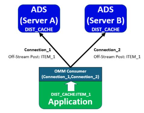
Figure 4: Off-stream posting to multiple servers
An application configures EMA with the request routing feature to connect to Server A and Server B, both of which offer the same posting service (DIST_CACHE). It then performs off-stream posting by posting an item (ITEM_1) to the DIST_CACHE service. With request routing enabled, EMA distributes the post message to the DIST_CACHE services on both servers.
The following section outlines the configuration settings and coding examples to help implement the request routing feature.
Configurations and Coding Examples
1. Request Routing Configurations
EMA supports request routing through configurable settings, enabling users to adjust application behavior by modifying these configurations.
| Configuration | Node | Descrription |
|---|---|---|
| SessionChannelSet | Consumer | Specifies a comma-separated set of session channel names (SessionChannelInfo). A connection to session channels in the set will be established simultaneously |
| SessionEnhancedItemRecovery | Consumer | Specifies that the Enterprise Message API should immediately attempt to recover the item, when the current connection goes down |
| SessionChannelList | SessionChannelGroup | Contains one or more SessionChannelInfo entries |
| Name | SessionChannelInfo | Specifies the name of this Session Channel component |
| ChannelSet | SessionChannelInfo | Specifies a comma-separated set of channels names. Channels in the set will be tried with each reconnection attempt until a successful connection is made |
Users can set the SessionChannelSet configuration in the Consumer and define the corresponding SessionChannelInfo for each connection. For example:
<EmaConfig>
<ConsumerGroup>
<DefaultConsumer value="Consumer_10"/>
<ConsumerList>
<Consumer>
<Name value="Consumer_10"/>
<SessionChannelSet value="Connection_1, Connection_2"/>
<SessionEnhancedItemRecovery value="1 "/>
<Dictionary value="Dictionary_2"/>
</Consumer>
</ConsumerList>
</ConsumerGroup>
...
<SessionChannelGroup>
<SessionChannelList>
<SessionChannelInfo>
<Name value="Connection_1"/>
<ChannelSet value="Channel_1"/>
</SessionChannelInfo>
<SessionChannelInfo>
<Name value="Connection_2"/>
<ChannelSet value="Channel_11"/>
</SessionChannelInfo>
</SessionChannelList>
</SessionChannelGroup>
...
<ChannelGroup>
<ChannelList>
<Channel>
<Name value="Channel_1"/>
<ChannelType value="ChannelType::RSSL_SOCKET"/>
<Host value="<Server A>"/>
<Port value="14002"/>
</Channel>
<Channel>
<Name value="Channel_11"/>
<ChannelType value="ChannelType::RSSL_SOCKET"/>
<Host value="<Server B>"/>
<Port value="14002"/>
</Channel>
</ChannelList>
</ChannelGroupt
...
<DictionaryGroup>
<DictionaryList>
<Dictionary>
<Name value="Dictionary_2"/>
<DictionaryType value="DictionaryType::FileDictionary"/>
<RdmFieldDictionaryFileName value="./RDMFieldDictionary"/>
<EnumTypeDefFileName value="./enumtype.def"/>
</Dictionary>
</DictionaryList>
</DictionaryGroup>
...
</EmaConfig>
The above configurations define Consumer_10, which sets the SessionChannelSet to route requests through Connection_1 and Connection_2. Connection_1 uses the Channel_1 configuration to connect to Server A, while Connection_2 uses the Channel_11 configuration to connect to Server B.
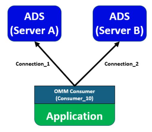
Figure 5: Request Routing ChannelSet Configurations
2. Service List
A Service List is a named collection of specific service names used to request items by referring to the list's name. The ServiceList class is used to define such a list. Before creating an OmmConsumer instance, applications must add ServiceList objects to an OmmConsumerConfig instance.
AppClient client;
ServiceList serviceList("SVG1");
serviceList.concreteServiceList().push_back("ELEKTRON_DD");
serviceList.concreteServiceList().push_back("IDN_RDF");
OmmConsumer consumer( OmmConsumerConfig().addServiceList(serviceList));
consumer.registerClient( ReqMsg().serviceListName( "SVG1" ).name( "LSEG.L" ), client );
The code creates a service list named SVG1, which includes the ELEKTRON_DD and IDN_RDF services. It then uses the OMMConsumerConfig::addServiceList method to attach this list to an OmmConsumerConfig instance during the initialization of an OMMConsumer. Finally, the application must use the service list name (SVG1) when making item requests.
3. Multiple Credentials
Typically, users can specify a username for server connections via an OmmConsumerConfig instance during the initialization of an OmmConsumer. This username will be applied to all connections established by that OmmConsumer instance.
For example, in the following code, all connections configured in Consumer_10 will use user01 as the login name.
OmmConsumer consumer(
OmmConsumerConfig()
.consumerName("Consumer_10")
.username("user01"));
However, users can specify a different username for each channel using the following approach:
void LoginClient::onLoginCredentialRenewal(const refinitiv::ema::access::OmmConsumerEvent&)
{
Login::LoginReq* credentials = (Login::LoginReq*)consumerEvent.getClosure();
LoginMsgCredentialRenewal credentialRenewal;
credentialRenewal.userName(const_cast <EmaString&>(credentials->getName()));
if (credentials->hasAuthenticationExtended())
credentialRenewal.authenticationExtended(const_cast <EmaBuffer&>(credentials->getAuthenticationExtended()));
pOmmConsumer->renewLoginCredentials(credentialRenewal);
}
int main( int argc, char* argv[] )
{
…
Login::LoginReq* login1 = new Login::LoginReq;
Login::LoginReq* login2 = new Login::LoginReq;
LoginClient loginClient;
login1->name("user01");
login2->name("user02");
OmmConsumer consumer( OmmConsumerConfig()
.addLoginMsgCredential(login1->getMessage(),"Channel_1", loginClient, (void*)login1)
.addLoginMsgCredential(login2->getMessage(), "Channel_11", loginClient), (void*)login2);
…
}
The code sets user01 for logging into Channel_1 and user02 for Channel_11. For more details, refer to the 480_MP_MultiCredentials example.
4. Session Channel Information
Applications can retrieve a list of session channels using the sessionChannelInfo() method, available from either the OmmConsumer or OmmConsumerEvent classes. This allows applications to monitor the state of each active session channel. A session channel is automatically removed from the list when it is closed by the Enterprise Message API or when the channel goes completely down.
To obtain the current session information, users must provide a List<ChannelInformation> as an argument to the method. The following sample code demonstrates how to iterate through the list of ChannelInformation objects returned by the function.
void AppClient::printSessionStatus(const refinitiv::ema::access::OmmConsumerEvent& event)
{
EmaVector<ChannelInformation> statusVector;
event.getSessionInformation(statusVector);
// Print out the channel information.
for (UInt32 i = 0; i < statusVector.size(); ++i)
{
cout << statusVector[i] << endl;
}
}
The output is:
channelName: Channel_1
sessionChannelName: Connection_1
hostname: 192.168.42.195
IP address: not available for OmmConsumer connections
port: 14002
connected component info:
channel state: active
connection type: socket
protocol type: Rssl wire format
…
ph detection time interval: 0
ph channel name: Channel_1
ph wsb channel name:
ph fall back with in WSB group: disabled
ph is channel preferred: non-preferred
ph remaining detection time: 0
channelName: Channel_11
sessionChannelName: Connection_2
hostname: 192.168.42.195
IP address: not available for OmmConsumer connections
port: 14003
connected component info: ads3.8.2.L1.linux.rrg 64-bit
channel state: active
connection type: socket
protocol type: Rssl wire format
major version: 14
minor version: 1
ping timeout: 30
…
ph wsb channel name:
ph fall back with in WSB group: disabled
ph is channel preferred: non-preferred
ph remaining detection time: 0
For more information, please refer to the 510_RequestRouting_FileCfg example in the Real-Time SDK package.
5. Connection Resilience Configurations
Users can configure request routing connections in the SessionChannelInfo configuration. This configuration supports server connection resilience configurations, such as fail-over, host, warm standby, and preferred host.
Fail-Over
The failover resilience mechanism can be configured using the ChannelSet, which specifies a comma-separated list of channel names. Each channel listed must have a corresponding entry in the ChannelGroup. The channels in the set will be tried sequentially until a successful connection is established. For example:
<SessionChannelGroup>
<SessionChannelList>
<SessionChannelInfo>
<Name value="Connection_1"/>
<ChannelSet value="Channel_1, Channel_2"/>
</SessionChannelInfo>
<SessionChannelInfo>
<Name value="Connection_2"/>
<ChannelSet value="Channel_11, Channel_12"/>
</SessionChannelInfo>
</SessionChannelList>
</SessionChannelGroup>
With the above configurations, Connection_1 utilizes Channel_1 and Channel_2 for failover, while Connection_2 relies on Channel_11 and Channel_12 for the same purpose.
Warm Standby
This warm standby feature provides the application with the capability to failover from an active to one or more standby server(s) if the active server fails. To use this feature, the following configurations can be used.
| Configuration | Node | Description |
|---|---|---|
| WarmStandbyChannelSet | SessionChannelInfo | Specifies a comma-separated set of WarmStandby channels names |
| StartingActiveServer | WarmStandbyChannel | Specifies a starting server information to establish an initial connection |
| StandbyServerSet | WarmStandbyChannel | Specifies a comma-separated set of warm standby server information to establish connection(s) |
| WarmStandbyMode | WarmStandbyChannel | Specifies the warm standby mode used by warm standby channel |
| Channel | WarmStandbyServerInfo | Specifies the channel that the warm standby channel should use |
| PerServiceNameSet | WarmStandbyServerInfo | Specifies a comma-separated set of preferred service name(s) for this server information |
The sample configurations are:
…
<SessionChannelGroup>
<SessionChannelList>
<SessionChannelInfo>
<Name value="Connection_1"/>
<WarmStandbyChannelSet value="WarmStandbyChannel_1"/>
</SessionChannelInfo>
<SessionChannelInfo>
<Name value="Connection_2"/>
<WarmStandbyChannelSet value="WarmStandbyChannel_2"/>
</SessionChannelInfo>
</SessionChannelList>
</SessionChannelGroup>
…
<WarmStandbyGroup>
<WarmStandbyList>
<WarmStandbyChannel>
<Name value="WarmStandbyChannel_1"/>
<StartingActiveServer value="Server_Info_1"/>
<StandbyServerSet value="Server_Info_2"/>
<WarmStandbyMode value="WarmStandbyMode::LOGIN_BASED"/>
</WarmStandbyChannel>
<WarmStandbyChannel>
<Name value="WarmStandbyChannel_2"/>
<StartingActiveServer value="Server_Info_11"/>
<StandbyServerSet value="Server_Info_12"/>
<WarmStandbyMode value="WarmStandbyMode::LOGIN_BASED"/>
</WarmStandbyChannel>
</WarmStandbyList>
</WarmStandbyGroup>
…
<WarmStandbyServerInfoGroup>
<WarmStandbyServerInfoList>
<WarmStandbyServerInfo>
<Name value="Server_Info_1"/>
<Channel value="Channel_1"/>
<PerServiceNameSet value=""/>
</WarmStandbyServerInfo>
<WarmStandbyServerInfo>
<Name value="Server_Info_2"/>
<Channel value="Channel_2"/>
<PerServiceNameSet value=""/>
</WarmStandbyServerInfo>
<WarmStandbyServerInfo>
<Name value="Server_Info_11"/>
<Channel value="Channel_11"/>
<PerServiceNameSet value=""/>
</WarmStandbyServerInfo>
<WarmStandbyServerInfo>
<Name value="Server_Info_12"/>
<Channel value="Channel_12"/>
<PerServiceNameSet value=""/>
</WarmStandbyServerInfo>
</WarmStandbyServerInfoList>
</WarmStandbyServerInfoGroup>
…
With the above configurations, Connection_1 uses Channel_1 for the active server and Channel_2 for the standby server. Similarly, Connection_2 uses Channel_11 for the active server and Channel_12 for the standby server. For more information regarding the Warm Standby feature, please refer to the following articles.
Preferred Host
The Preferred Host feature allows consumer applications to designate a specific host or warm standby group as the preferred connection. When configured, the APIs can switch back to the preferred host or preferred warm standby group based on a timer or a direct function call.
This feature can be applied to the fail-over resilience mechanism by setting a channel as a preferred host by using the EnablePreferredHostOptions and PreferredChannelName configurations. For example:
<SessionChannelGroup>
<SessionChannelList>
<SessionChannelInfo>
<Name value="Connection_1"/>
<ChannelSet value="Channel_1, Channel_2"/>
<EnablePreferredHostOptions value="1"/>
<PreferredChannelName value="Channel_1"/>
<PHDetectionTimeInterval value="30"/>
</SessionChannelInfo>
<SessionChannelInfo>
<Name value="Connection_2"/>
<ChannelSet value="Channel_11, Channel_12"/>
<EnablePreferredHostOptions value="1"/>
<PreferredChannelName value="Channel_11"/>
<PHDetectionTimeInterval value="30"/>
</SessionChannelInfo>
</SessionChannelList>
</SessionChannelGroup>
The above configurations enable the preferred host feature on the Connection_1 and Connection_2. The Channel_1 is a preferred host for the Connection_1 and the Channel_11 is a preferred host for the Connection_2. Both connections uses a time-based interval of 30 seconds to trigger the preferred host fallback mechanism.
This feature can also be applied to the Warm Standby by setting an active server as a preferred host by using the EnablePreferredHostOptions and PHFallBackWithInWSBGroup configurations. For example:
…
<SessionChannelGroup>
<SessionChannelList>
<SessionChannelInfo>
<Name value="Connection_1"/>
<WarmStandbyChannelSet value="WarmStandbyChannel_1"/>
<EnablePreferredHostOptions value="1"/>
<PHFallBackWithInWSBGroup value="1"/>
<PHDetectionTimeInterval value="30"/>
</SessionChannelInfo>
<SessionChannelInfo>
<Name value="Connection_2"/>
<WarmStandbyChannelSet value="WarmStandbyChannel_2"/>
<EnablePreferredHostOptions value="1"/>
<PHFallBackWithInWSBGroup value="1"/>
<PHDetectionTimeInterval value="30"/>
</SessionChannelInfo>
</SessionChannelList>
</SessionChannelGroup>
…
<WarmStandbyGroup>
<WarmStandbyList>
<WarmStandbyChannel>
<Name value="WarmStandbyChannel_1"/>
<StartingActiveServer value="Server_Info_1"/>
<StandbyServerSet value="Server_Info_2"/>
<WarmStandbyMode value="WarmStandbyMode::LOGIN_BASED"/>
</WarmStandbyChannel>
<WarmStandbyChannel>
<Name value="WarmStandbyChannel_2"/>
<StartingActiveServer value="Server_Info_11"/>
<StandbyServerSet value="Server_Info_12"/>
<WarmStandbyMode value="WarmStandbyMode::LOGIN_BASED"/>
</WarmStandbyChannel>
</WarmStandbyList>
</WarmStandbyGroup>
…
<WarmStandbyServerInfoGroup>
<WarmStandbyServerInfoList>
<WarmStandbyServerInfo>
<Name value="Server_Info_1"/>
<Channel value="Channel_1"/>
<PerServiceNameSet value=""/>
</WarmStandbyServerInfo>
<WarmStandbyServerInfo>
<Name value="Server_Info_2"/>
<Channel value="Channel_2"/>
<PerServiceNameSet value=""/>
</WarmStandbyServerInfo>
<WarmStandbyServerInfo>
<Name value="Server_Info_11"/>
<Channel value="Channel_11"/>
<PerServiceNameSet value=""/>
</WarmStandbyServerInfo>
<WarmStandbyServerInfo>
<Name value="Server_Info_12"/>
<Channel value="Channel_12"/>
<PerServiceNameSet value=""/>
</WarmStandbyServerInfo>
</WarmStandbyServerInfoList>
</WarmStandbyServerInfoGroup>
…
With the above configurations, Connection_1 uses Channel_1 for the active server and Channel_2 for the standby server. Similarly, Connection_2 uses Channel_11 for the active server and Channel_12 for the standby server. In both cases, the active servers (Channel_1 and Channel_11) correspond to the preferred host for each connection. For more information regarding the preferred host feature, please refer to this Introduction to the Real-Time SDK Preferred Host Feature article.
Summary
Request Routing in EMA consumer applications enables multiple connections to upstream servers and intelligently directs market data item requests based on each server’s availability and operational status. It supports both posting and service lists, named groupings of servers that can be referenced in item requests. The SDKs use these lists to route requests to the appropriate service, following a predefined sequence of service names and connection configurations. This feature can be integrated with other connection resilience mechanisms such as fail-over, warm standby, and preferred host, all of which can be configured via a user-defined EMA configuration file.
Get In Touch
Related APIs
Related Articles
-
Introduction to the Refinitiv Real-Time SDK Warm Standby Feature
-
How to Run Refinitiv Real-Time SDK C/C++ Warm Standby Examples
-
Introduction to Interactive Source Blending (ISB) feature in ADH 3.0 or above using EMA C++
-
Resiliency in real-time feed applications
-
Learn how to create auto-expiring records on Refinitiv Real-Time
-
Publish Custom Data via Refinitiv Real-Time Distribution System by EMA
-
Introduction to the Real-Time SDK Preferred Host Feature
Introduction to the Real-Time SDK Request Routing Feature
Request Free Trial
Call your local sales team
Americas
All countries (toll free): +1 800 427 7570
Brazil: +55 11 47009629
Argentina: +54 11 53546700
Chile: +56 2 24838932
Mexico: +52 55 80005740
Colombia: +57 1 4419404
Europe, Middle East, Africa
Europe: +442045302020
Africa: +27 11 775 3188
Middle East & North Africa: 800035704182
Asia Pacific (Sub-Regional)
Australia & Pacific Islands: +612 8066 2494
China mainland: +86 10 6627 1095
Hong Kong & Macau: +852 3077 5499
India, Bangladesh, Nepal, Maldives & Sri Lanka:
+91 22 6180 7525
Indonesia: +622150960350
Japan: +813 6743 6515
Korea: +822 3478 4303
Malaysia & Brunei: +603 7 724 0502
New Zealand: +64 9913 6203
Philippines: 180 089 094 050 (Globe) or
180 014 410 639 (PLDT)
Singapore and all non-listed ASEAN Countries:
+65 6415 5484
Taiwan: +886 2 7734 4677
Thailand & Laos: +662 844 9576